Watch the the finished product in action
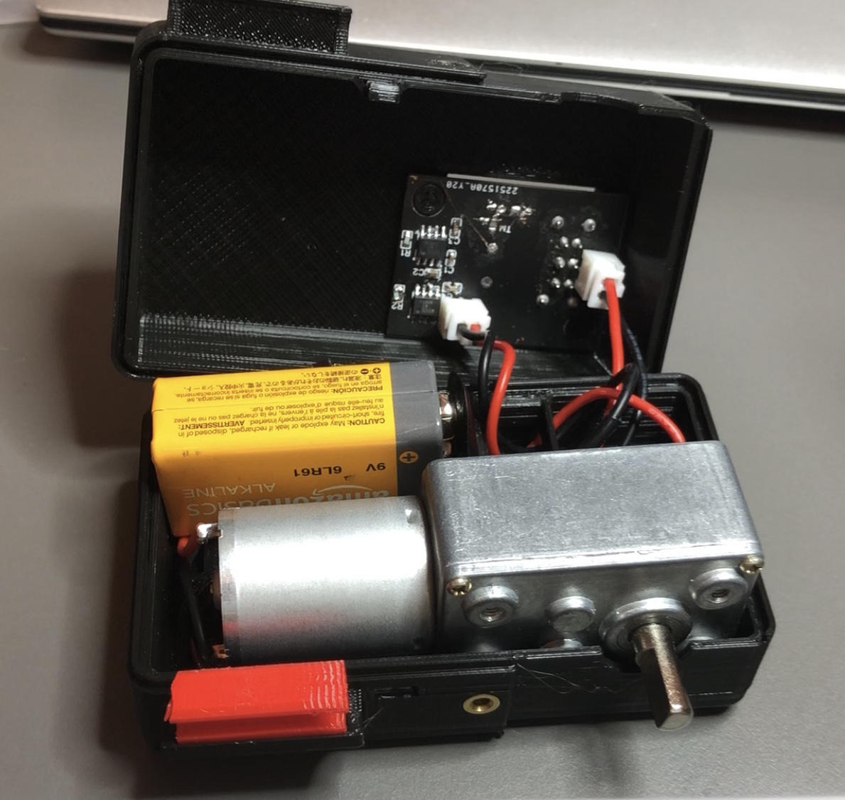
Inside the box... 9V battery, DC motor, and PCB.
Half of the separating motor clamp is glued to the shaft of the DC motor, the other half is snapped into place after the tubing is in place.
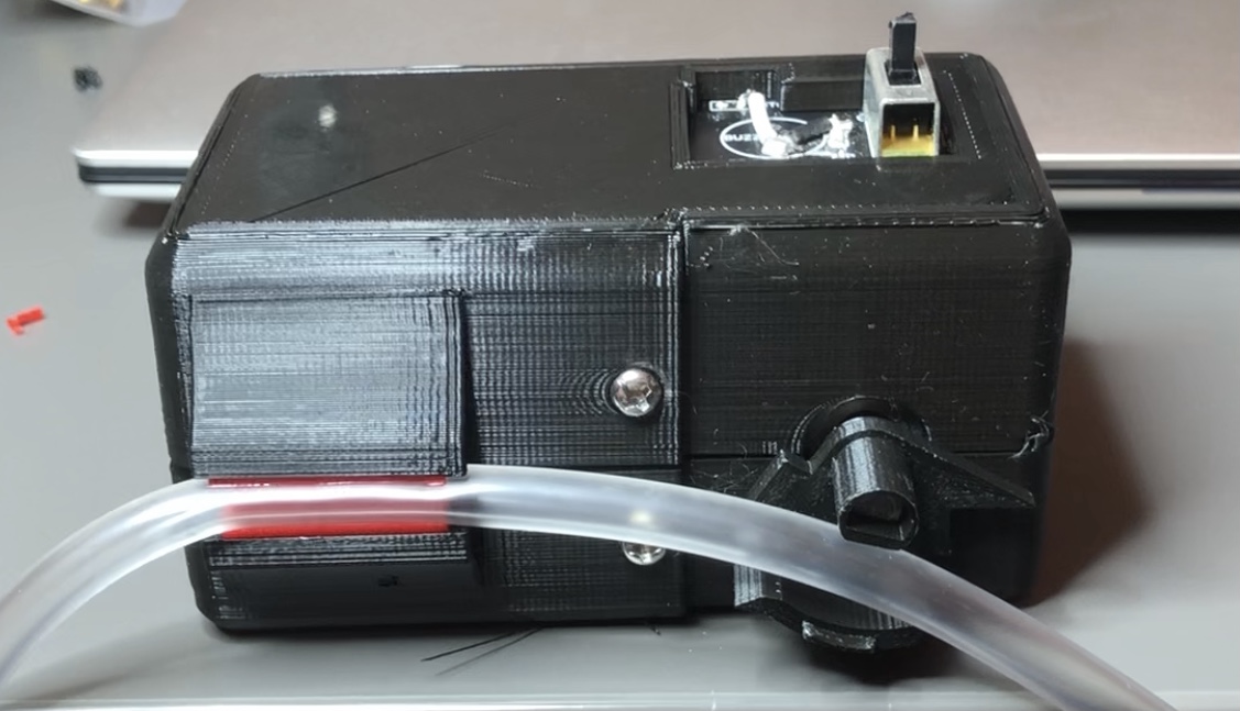
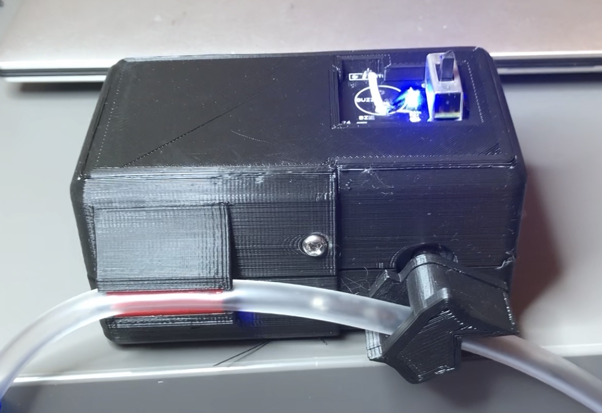
Here is the clamping mechanism closeup in action.
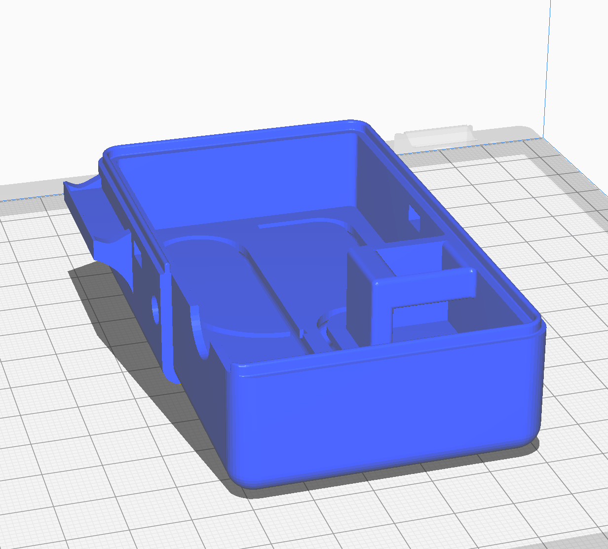
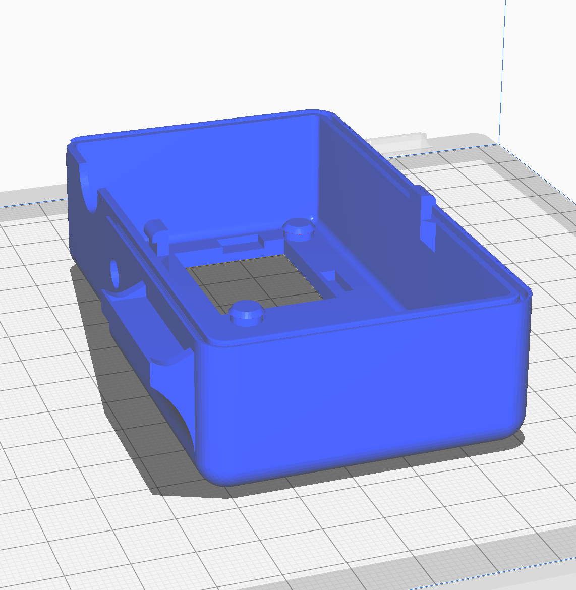
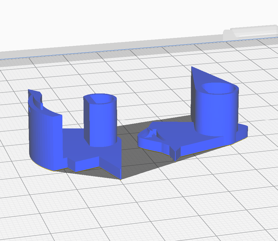
This is the 3D file ready to be printed.
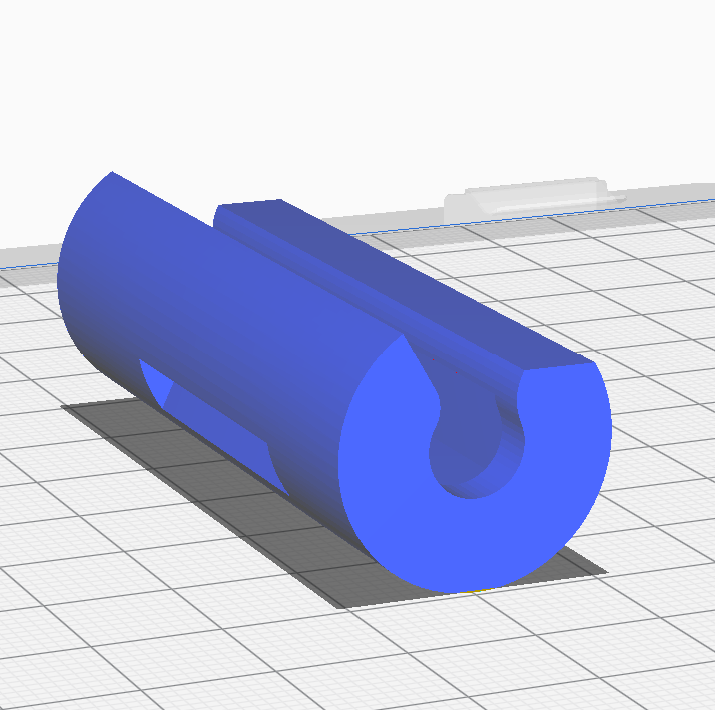
This is the separating motor clamp 3D file.
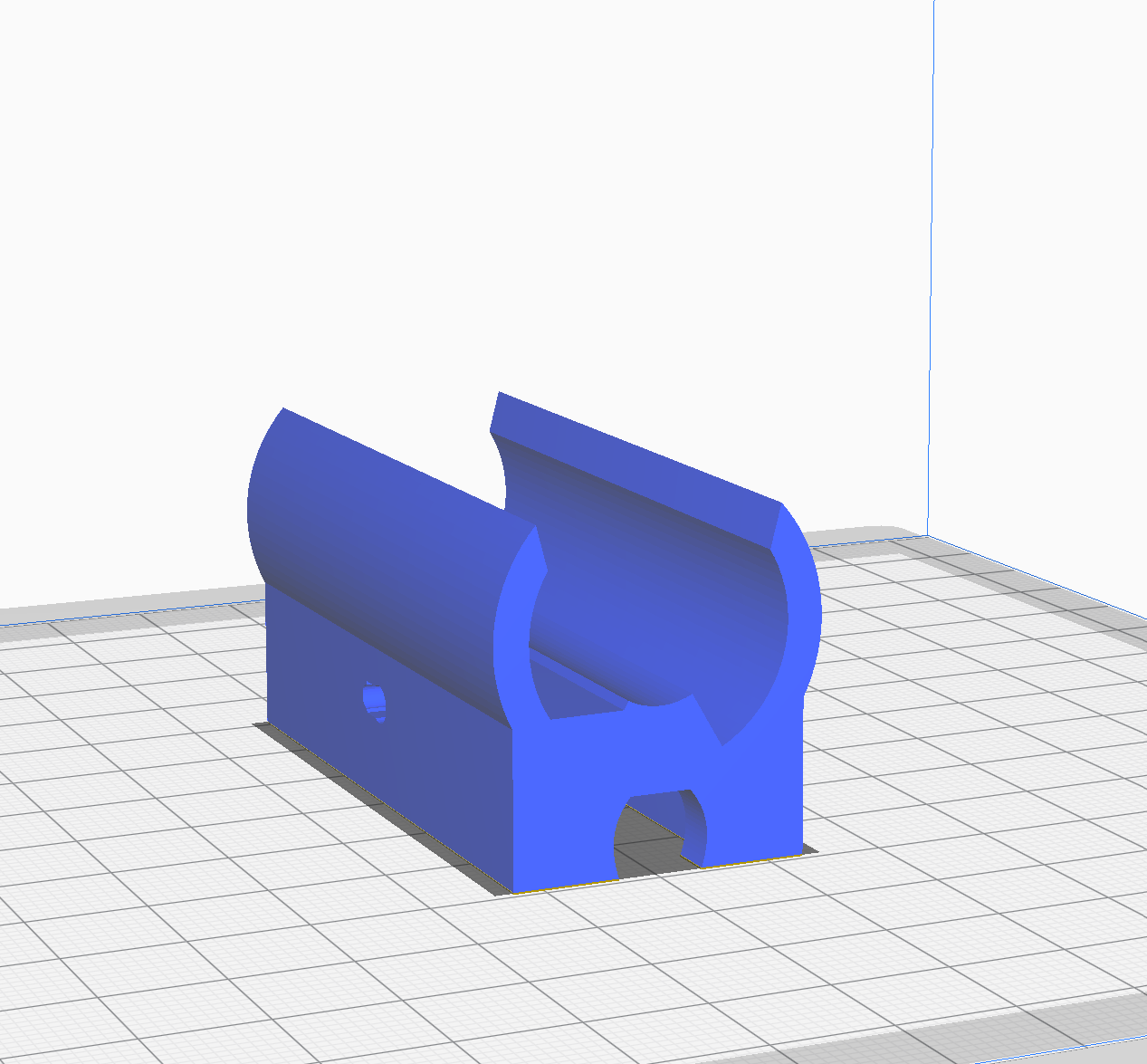
This is the reed switch and a magnet housing that attaches to both tubings to detect VND
The Reed and Magnet housing 3D files ready to be printed
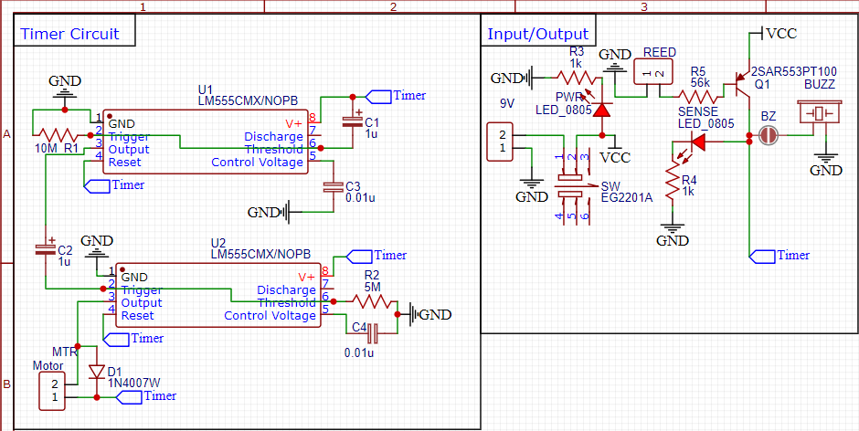
The PCB is analog. A reed switch inside the tube housing activates a transistor which provides power to a LM555 timer. The timer triggers the motor which clamps the tubing. The time delay limits false positives.
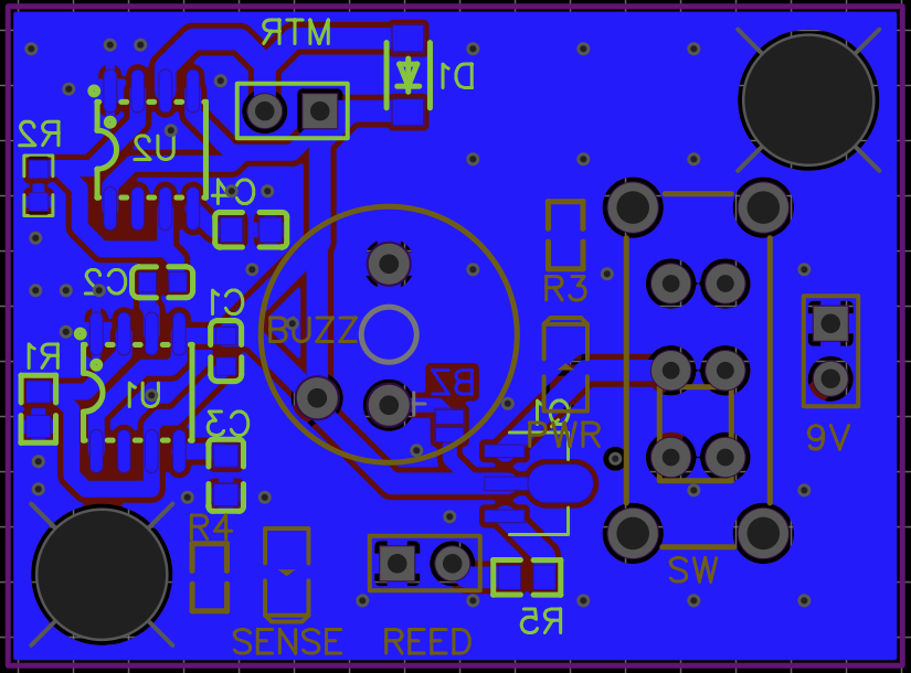
PCB Backside
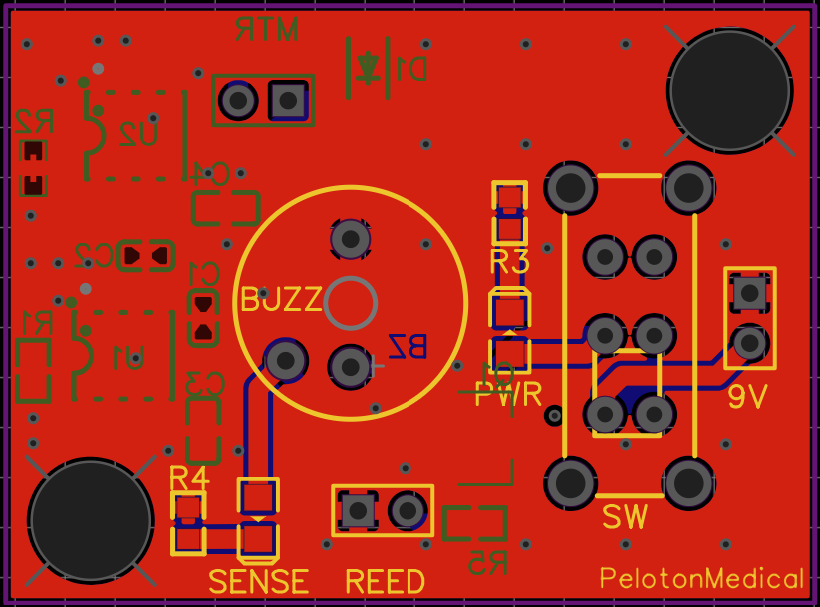
PCB Frontside
Schematic